D3 IST1

Application-

Instrumentation Panels
Control Desk
PLC / DCS / SCADA Automation Systems
Measurement & Control Panels

Overview-

Signal Isolation transducer
Input & output DC signals
Single or dual outputs
Accuracy 0.5%
Operations
The input signal is filtered and processed to convert into a standard dc voltage. This voltage is fed to a linear optocoupler which provides the required galvanic isolation. An optical feedback is used for improved linearity, response time and temperature effects. The output from the linear optocoupler is further processed to provide dc voltage / current output.

The isolator with fast response time (10 mSec) are typically used in feedback control system.

In input dc current is chopped by the chopper to convert it into high frequency ac signal. This signal is fed to an isolating high frequency transformer. The ac output current from the transformer is rectified and filtered to obtain load independent dc output current. As the transformation ratio is 1:1 the output current is identical in value to the dc input current.

Description

Technical Specifications

Supply Voltage

Auxiliary Supply Self Powered, 110/240 V AC, 24 / 48 / 110 / 220 V DC ± 20 %

Power Consumption
Power Consumption 3.5 VA – AC, 4 VA – DC

Input Value
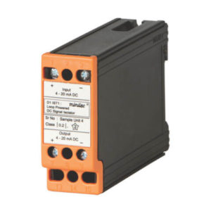
I in 4 – 20 mA DC Single
V in 0-50, 0-60, 0-75, 0-100 mV DC / 0-1, 0-5, 0-10, 0-150, 0-300, 0-600 V DC

Resistance Type
Resistance Type N.A.

DC Output (Single / Dual)
DC Output (Single / Dual) 0 – 1 mA, 0 – 10 mA, 0 – 20 mA, 4 – 20 mA, 0 – 5 V, 0 – 10 V

No of Signal Output
No of Signal Output Single (Optional Dual Output)

Response Time
Response Time 500 mSec.

Input / Output isolation
Input / Output isolation Galvanic

Temperature
Temperature 0°C to + 55°C

Humidity
Humidity Up to 95% Rh non condensing

Dimensions (L x W x D) (mm)
Dimensions (L x W x D) (mm) 73 x 83.5 x 117.5

Weight
Weight 1200 gms.