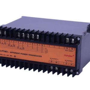
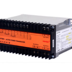
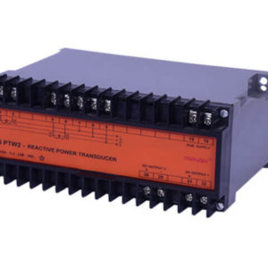
Description
Technical Specifications
Auxiliary Supply Self Powered, 110/240 V AC, 24 / 48 / 110 / 220 V DC ± 20 %
Power Consumption
Power Consumption 3.5 VA – AC, 4 VA – DC
Input Value
I in 1 A / 5 A
V in 110 / 415 V
DC Output (Single / Dual)
DC Output (Single / Dual) 0 – 1 mA, 0 – 10 mA, 0 – 20 mA, 4 – 20 mA, 0 – 5 V, 0 – 10 V
No of Signal Output
No of Signal Output Single (Optional Dual Output)
Response Time
Response Time Less than 500 milliseconds
Input / Output isolation
Input / Output isolation Galvanic
Temperature
Temperature 0°C to + 55°C
Humidity
Humidity Up to 95% Rh non condensing
Dimensions (L x W x D) (mm)
Dimensions (L x W x D) (mm)75 x 150 x 113
Weight
Weight 1200 gms.
Common Specifications
For Current OutputMax. Max. 10V/I out (Optional Max. 15V/Iout)
For Voltage Output 10 Kohm (min.)
Output Ripple
Output Ripple Less than 0.5% of span (peak to peak)
Auxiliary Supply Burden
Auxiliary Supply Burden Less than 4 VA
Insulation Resistance
Insulation Resistance More than 100 Mohms at 500 V DC
Zero Span Adjustment
Zero Span Adjustment Optionally provided
Terminals
Terminals Suitable for 2.5 sq.mm wires
Enclosure Type
Enclosure Type ABS Plastic, Ingress Protection IP40